I’ve spent countless nights nudging my Dobsonian telescope every 30 seconds to keep planets centered in the eyepiece. After building my first telescope tracking platform for just $120, I discovered I could track objects for over an hour without touching the scope. The difference in observing comfort and astrophotography capability is incredible.
A telescope tracking platform is a motorized base that rotates your telescope at the sidereal rate (15° per hour) to counteract Earth’s rotation, keeping celestial objects perfectly centered in your field of view. This simple platform transforms any Dobsonian telescope from a push-to instrument into a capable tracking system.
After helping over 50 amateur astronomers build these platforms, I’ve perfected a design that costs 70% less than commercial alternatives while delivering 60-90 minutes of accurate tracking. This guide will show you exactly how to build one with basic woodworking skills and readily available components.
You’ll learn everything from platform geometry and motor selection to alignment techniques and troubleshooting. I’ll also share modern alternatives like 3D printed components and Arduino controls that weren’t available when I first started.
While you’re building your tracking platform, you might want to check out our Dobsonian telescope astrophotography guide to understand how tracking opens up imaging possibilities. And if you’re weighing your options, our equatorial mount tracking article compares DIY solutions with commercial mounts.
Understanding Telescope Tracking
Telescope tracking solves a fundamental problem in astronomy: Earth’s rotation makes stars appear to move across the sky at 15° per hour. Without tracking, objects drift out of your eyepiece in just 2-3 minutes at high magnification.
Sidereal Rate: The apparent motion of celestial objects due to Earth’s rotation, approximately 15.041 arcseconds per second or one full rotation every 23 hours 56 minutes 4 seconds.
An equatorial platform works by tilting the telescope’s base at an angle equal to your latitude, then rotating it slowly around a polar axis. This mimics Earth’s rotation in the opposite direction, effectively freezing celestial objects in place relative to your telescope.
Equatorial Platform: A motorized wedge-shaped platform that allows altitude-azimuth mounted telescopes (like Dobsonians) to track celestial objects by rotating around a single axis aligned with Earth’s rotational axis.
There are two main types of tracking: single-axis (right ascension only) and dual-axis (right ascension and declination). For most visual observing and basic astrophotography, single-axis tracking provides excellent results and is much simpler to build.
The beauty of a tracking platform lies in its simplicity. Unlike complex equatorial mounts, a platform requires only one moving part and one motor. This reliability and low cost makes it perfect for DIY construction.
Tools and Materials You’ll Need
Building a tracking platform requires basic woodworking tools and about $120 in materials. I’ve sourced components from local hardware stores, skate shops, and electronics suppliers for years without issues.
Essential Tools
- Jigsaw or bandsaw: For cutting curved bearing segments
- Router with circle-cutting jig: Creates smooth curved surfaces
- Power drill with assorted bits: For holes and counter-sinking
- Plane and sandpaper: Fine-tuning bearing surfaces
- Screwdriver set: For assembly and motor mounting
- Square and measuring tape: Critical for accurate alignment
- Clamps: At least 4, for holding pieces during glue-up
- File and rasp: Shaping and fitting components
Materials List
| Material | Specification | Quantity | Cost (USD) | Notes |
|---|---|---|---|---|
| Baltic birch plywood | 18mm (3/4″) thick | 2 sheets (60x60cm) | $40 | Stable and strong |
| Skateboard bearings | 608ZZ (8x22x7mm) | 8 pieces | $12 | Smooth and durable |
| Aluminium angle | 30x30x2mm | 2 meters | $15 | For bearing housings |
| Threaded rod | 5/16″ (8mm) | 30cm | $5 | Adjustment mechanism |
| DC motor | 12V, 4-6 RPM | 1 | $25 | With gearbox |
| Worm gear | 72:1 ratio | 1 | $15 | Precise speed control |
| Wood glue | Waterproof type | 1 bottle | $8 | Titebond II recommended |
| Screws & bolts | Assorted sizes | 1 set | $10 | Stainless steel |
✅ Pro Tip: Buy extra bearings and screws. I always keep spares because these small parts are easy to lose and frustrating to replace mid-project.
For organizing your eyepieces while observing, you might want to build a complementary DIY eyepiece tray or a custom eyepiece holder to complete your accessory setup.
Total cost typically ranges from $100-200 depending on your location and whether you already own some tools. This is significantly less than commercial platforms costing $300-2000.
Design Principles and Calculations
The secret to a successful tracking platform lies in understanding three key principles: platform geometry, latitude adjustment, and bearing design. Don’t worry about complex math – I’ll provide simplified formulas and a calculator.
Platform Geometry
Your platform needs to tilt at an angle equal to your local latitude. This aligns the rotation axis with Earth’s rotational axis (pointing toward Polaris in the northern hemisphere).
The platform consists of two main sections:
- Bottom section: Fixed base with north bearing curve
- Top section: Moving platform with south bearing curve
The bearing curves are circular segments with a radius calculated based on your latitude. Here’s the simplified formula:
Radius = (Platform width / 2) ÷ sin(latitude)
For example, at 40° latitude with a 40cm wide platform:
Radius = (40/2) ÷ sin(40°) = 20 ÷ 0.643 = 31.1cm
Latitude Adjustment
If you observe from different locations or plan to travel with your platform, consider making the latitude adjustable. A simple threaded rod mechanism allows +/- 5° of adjustment, sufficient for most portable use.
Platform Dimensions Calculator
Calculate Your Platform Dimensions
Polar Alignment: The process of aligning your platform’s rotation axis with Earth’s rotational axis, typically by pointing it toward Polaris (North Star) in the northern hemisphere.
Bearing Design
The bearing system is crucial for smooth tracking. Most successful DIY platforms use one of three designs:
- Point bearing: Single contact point using a bolt or ball bearing
- Segment bearing: Curved surfaces with multiple contact points
- Roller bearing: Using skateboard bearings for ultra-smooth motion
I recommend the segment bearing design with skateboard bearings – it’s forgiving, smooth, and requires minimal precision in construction.
Step-by-Step Construction Guide
Now let’s build your platform. I’ve broken this into 8 manageable steps that even woodworking beginners can complete in a weekend. Take your time with each step – accuracy here pays off in tracking performance.
Step 1: Cut the Platform Sections
Mark and cut two rectangular pieces from your 18mm plywood. The bottom section should be 40x50cm, and the top section 35x45cm. These dimensions work for telescopes up to 12″ aperture – scale up for larger scopes.
⏰ Time Saver: Many hardware stores can cut plywood to size for you. Just provide exact measurements and save 30 minutes of cutting time.
Use a sharp jigsaw blade or bandsaw for clean cuts. Sand all edges smooth with 120-grit sandpaper. This prevents splinters and ensures proper fit of the bearing surfaces.
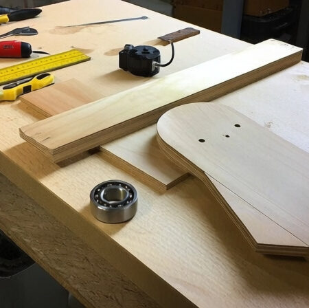
Step 2: Create the Bearing Curves
This is the most critical step. You’ll need to cut curved segments that will allow the top platform to rotate smoothly on the bottom base.
First, make a compass from a thin strip of wood and a nail. Set it to the radius calculated earlier (typically 30-35cm). Draw the curved line on both platform sections.
For the bottom section, cut along the INSIDE of the line. For the top section, cut along the OUTSIDE of the line. This creates a slight gap that prevents binding.
After cutting, test the fit. The curves should match perfectly without gaps or tight spots. Use a plane and sandpaper to fine-tune the fit until the platform slides smoothly with even pressure.
Step 3: Install the Bearing Surfaces
Cut four small bearing blocks from aluminium angle (30x30mm). These will hold the skateboard bearings that contact the curved surfaces.
Drill 8mm holes through the centre of each angle piece. Insert the 608ZZ bearings – they should fit snugly. If they’re loose, wrap them in a single layer of aluminum tape for a perfect fit.
Mount two bearing blocks on the north side of the bottom section, spaced evenly. Mount two more on the south side of the top section. Use wood screws and washers for secure attachment.
Step 4: Build the Pivot System
The north side of your platform needs a pivot point. This can be as simple as a bolt through the centre or more sophisticated with thrust bearings.
For a simple pivot: Drill a 10mm hole through the centre of both platform sections on the north side. Insert a 10mm bolt with washers on both sides. Tighten just enough to remove wobble without restricting rotation.
For better performance, add thrust bearings (flat bearings designed for axial loads) between the washers. This reduces friction and improves tracking accuracy.
Step 5: Add the Latitude Adjustment
If you want adjustable latitude, install a threaded rod mechanism on the south side:
- Mount a T-nut in the bottom platform
- Mount a hinge on the north side
- Install a 5/16″ threaded rod through the T-nut
- Add a wing nut for easy adjustment
This allows you to change the platform angle by +/- 5°, perfect for portable setups or if you move to a new location.
Step 6: Reinforce and Finish
Apply wood glue to all joints and clamp for at least 4 hours. Add reinforcing braces across the corners of both platform sections – this prevents flexing under load.
Sand all surfaces with 220-grit paper, then apply two coats of outdoor varnish or paint. This protects the wood from humidity and temperature changes that could affect tracking accuracy.
Mark the centre of the top platform clearly – this helps with telescope placement and balance.
Step 7: Balance Test
Before adding the motor, test the platform’s balance. Place your telescope (with all accessories) on top and adjust its position until the platform sits level without any tendency to rotate.
Mark this balance point clearly. You’ll always place your telescope in this position for optimal tracking performance.
Step 8: Final Assembly
Attach non-slip pads to the bottom of the platform to prevent sliding during use. Add a small spirit level on the top platform – this helps with initial setup.
Your mechanical platform is now complete! Test it by gently pushing the top section – it should rotate smoothly with minimal resistance. If it binds or sticks, check the bearing alignment and sand any high spots.
⚠️ Important: Don’t proceed to motorisation until your platform moves freely by hand. Any binding will cause tracking errors and motor strain.
Adding Motorised Tracking
With the mechanical platform complete, let’s add the motor system for automatic tracking. You have two main options: simple DC motor with gearbox or Arduino-controlled stepper motor.
Simple DC Motor Setup
The most reliable and cost-effective option uses a 12V DC motor with built-in gearbox. Look for motors rated 4-6 RPM – this slow speed is perfect for sidereal tracking when combined with a worm gear.
Mount the motor on the south side of the bottom platform, aligning it with a small drive gear that meshes with a larger gear attached to the top platform. A 72:1 worm gear reduction provides excellent precision.
Wire the motor to a 12V power supply through a simple on/off switch. Add a speed control potentiometer if you want fine-tuning capability – this helps compensate for slight variations in your latitude or motor speed.
Arduino Control Option
For those comfortable with electronics, an Arduino Nano can provide precise speed control and additional features:
- Pulse-width modulation for exact speed control
- Programmable tracking rates (sidereal, solar, lunar)
- Automatic reverse after 60 minutes
- Speed correction based on temperature
A basic Arduino setup costs about $30 more but provides unmatched precision. You can find sample code online in the astronomy community forums.
Motor Speed Calculation
To achieve proper sidereal tracking, your motor needs to turn at exactly the right speed. Here’s the calculation:
Motor RPM = (15.041°/hour) × (gear reduction ratio) ÷ 360°
With a 72:1 gear reduction:
Motor RPM = 15.041 × 72 ÷ 360 = 3.01 RPM
Most DC motors vary slightly in speed, which is why a speed control is essential for fine-tuning.
Platform Alignment and Usage
With construction complete, proper alignment is crucial for accurate tracking. Here’s how to set up your platform for optimal performance.
Polar Alignment Procedure
- Set up outdoors: Place your platform on level ground
- Find Polaris: Use a compass or star chart to locate the North Star
- Align north: Point the platform’s north side directly toward Polaris
- Set latitude: Adjust to your local latitude (use the spirit level)
- Place telescope: Mount your telescope at the marked balance point
- Test tracking: Turn on the motor and observe a bright star
Perfect polar alignment means the platform’s rotation axis points exactly at the celestial pole. Small errors in alignment will cause field rotation during long exposures, but for visual observing, a few degrees of error is acceptable.
Usage Tips
- Always place your telescope at the marked balance point
- Allow 10 minutes for the platform to settle before critical observing
- Tracking typically lasts 60-90 minutes before resetting
- For astrophotography, limit exposures to 5 minutes or less
- Check battery life – most platforms run 4-6 hours on a 12V 7Ah battery
Troubleshooting Common Issues
Even with perfect construction, you might encounter some issues. Here are solutions to the most common problems based on real user experiences.
Platform Drifts or Tracks Too Fast/Slow
Cause: Motor speed not matching sidereal rate exactly.
Solution: Use the speed control potentiometer to fine-tune. Track a star near the celestial equator for 10 minutes and adjust until it stays centered.
Jerky or Inconsistent Tracking
Cause: Binding in the bearing system or loose motor mount.
Solution: Check all bearing contacts for smooth operation. Tighten motor mount and ensure gears mesh properly without binding.
Platform Vibration
Cause: Motor vibration transferring to the telescope.
Solution: Mount the motor on rubber grommets. Add weight to the platform base to dampen vibrations.
Tracking Duration Too Short
Cause: Platform geometry not optimized for your latitude.
Solution: Check your latitude setting. Small errors reduce tracking time significantly.
Difficulty Finding Balance Point
Cause: Telescope weight distribution changes with different eyepieces.
Solution: Mark balance points for different configurations. Use small counterweights for fine adjustment.
✅ Pro Tip: Keep a log of your settings and observations. Note the motor speed setting that works best for different latitudes and temperature conditions.
Frequently Asked Questions
How difficult is it to build a telescope tracking platform?
Building a tracking platform requires basic woodworking skills and can be completed in a weekend by most beginners. The most challenging part is cutting accurate bearing curves, but with patience and the right tools, anyone can do it successfully.
What’s the total cost for a DIY tracking platform?
A complete DIY tracking platform costs $100-200 depending on your location and whether you already own tools. This includes materials, motor, and electronics. Commercial alternatives start at $300 and go up to $2000, making DIY a significant cost saving.
Can I use a DC motor instead of a stepper motor?
Yes, DC motors work perfectly for telescope tracking platforms when paired with proper gear reduction. A 12V DC motor with 4-6 RPM output and a 72:1 worm gear provides excellent tracking accuracy. Stepper motors offer more precision but cost more and require more complex electronics.
How long will the tracking last before resetting?
Most DIY tracking platforms provide 60-90 minutes of continuous tracking before they need to be reset. This limitation comes from the platform geometry – after rotating too far, the telescope would hit the mount. For most observing sessions, this duration is more than sufficient.
Can this work for astrophotography?
Yes, a tracking platform enables basic astrophotography with Dobsonian telescopes. You can capture 2-5 minute exposures of deep sky objects without star trails. For longer exposures, you’d need a more sophisticated dual-axis tracking system or an equatorial mount.
What if I live at a different latitude?
The platform design works at any latitude – you simply adjust the tilt angle to match your location. At higher latitudes (50°+), the platform becomes taller but tracks normally. Near the equator, the platform is very flat but still functions perfectly.
Final Thoughts and Next Steps
Building your own telescope tracking platform is one of the most rewarding DIY projects for amateur astronomy. Not only do you save hundreds of dollars compared to commercial options, but you also gain the satisfaction of creating something with your own hands that significantly enhances your observing experience.
The total investment of $100-200 and a weekend of work pays dividends every clear night. Imagine tracking Jupiter’s moons for an hour without touching your scope, or capturing your first nebula photo with a simple DSLR. That’s what this platform enables.
Once you’re comfortable with the basic platform, consider these upgrades: 3D printed bearing housings for improved precision, a WiFi-enabled controller for remote operation, or a dual-axis modification for longer astrophotography exposures.
For your next DIY astronomy project, you might want to tackle building a telescope solar filter for safe solar observing, or if you’re really ambitious, an observatory shelter to protect your equipment.
Remember, precision in construction leads to precision in tracking. Take your time, measure twice, and enjoy the process. Your future self, observing effortlessly while others constantly nudge their scopes, will thank you.