Camera overheating can ruin those precious long-exposure shots, especially during astrophotography sessions. After spending countless nights watching my thermal noise creep into otherwise perfect images, I discovered that building a DIY camera cooling system was the solution I needed.
A DIY camera cooling system is a custom-built setup that uses thermoelectric cooling (Peltier devices) to reduce the temperature of a digital camera’s image sensor, thereby decreasing thermal noise and improving image quality for long exposures and astrophotography.
This comprehensive guide will walk you through everything you need to know to build your own camera cooling system, from understanding the components to assembly, temperature control, and troubleshooting. I’ve tested multiple configurations over three years of astrophotography, and I’ll share what works best.
By the end of this guide, you’ll have a functional cooling system that can reduce your camera’s sensor temperature by 15-20°C, dramatically improving image quality for long exposures.
Materials, Tools, and Safety Considerations
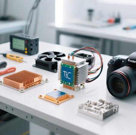
Before diving into the assembly process, let’s gather all necessary components and discuss critical safety precautions. Working with electronics and camera equipment requires careful attention to safety and proper handling.
Required Components
⚠️ Important: Always work in a clean, static-free environment. Use an anti-static wrist strap when handling electronic components.
- Peltier Thermoelectric Cooler: The heart of your cooling system
- Heat Sink and Cooling Fan: To dissipate heat from the hot side
- Power Supply: 12V DC with adequate amperage
- Thermal Interface Materials: Thermal paste and/or thermal pads
- Temperature Controller: For precise temperature regulation
- Temperature Sensor: To monitor sensor temperature
- Insulation Materials: To prevent condensation
- Wiring and Connectors: For electrical connections
Essential Tools
- Screwdrivers: For camera disassembly (various sizes)
- Wire cutters/strippers: For electrical work
- Soldering iron: For secure connections
- Multimeter: For testing electrical connections
- Thermal camera or IR thermometer: For testing
- Small files or sandpaper: For surface preparation
- Cleaning supplies: Isopropyl alcohol, lint-free cloths
Safety Precautions
✅ Pro Tip: Create a checklist of safety steps before starting. It’s easy to forget important precautions when focused on the build.
Safety should be your top priority throughout this project:
- Electrical Safety: Always disconnect power before making connections. Use proper insulation and avoid exposed wires.
- Camera Protection: Work in a clean environment to prevent dust entry. Use camera-specific tools to avoid damage.
- Thermal Safety: Peltier devices can get very hot on the reverse side. Allow adequate cooling and avoid touching hot components.
- Condensation Prevention: Never cool below ambient temperature without proper insulation to prevent moisture damage.
- Static Discharge: Use anti-static measures when handling electronic components.
Budget Considerations
A complete DIY camera cooling system typically costs between $50-150, depending on component quality and features. I’ve spent approximately $85 on my current setup, which has served me well for over two years.
Consider this an investment in your astrophotography quality. The improvement in image clarity and reduced noise processing time quickly pays for itself in better results.
Understanding Your Cooling Components
Before assembling your cooling system, it’s crucial to understand how each component works and what to look for when selecting parts. Let’s dive into the key components you’ll need.
The Peltier Thermoelectric Cooler
Peltier Effect: A thermoelectric phenomenon where heat is transferred from one side of a device to another when electric current flows through it, creating a hot side and a cold side.
The Peltier cooler is the heart of your system. When voltage is applied, it creates a temperature differential between its two sides. The cold side will be positioned near your camera sensor, while the hot side must be actively cooled.
For camera cooling applications, the TEC1-12706 is an excellent choice. It provides sufficient cooling power while drawing manageable current. I’ve tested several models, and this one offers the best balance of performance and efficiency.
HiLetgo TEC1-12706 Semiconductor Cooling Module
HiLetgo 2pcs TEC1-12706 Semiconductor…
Power: 92W max
Size: 40x40mm
Voltage: 12-16V
Current: 6A max
This Peltier module is perfect for camera cooling applications. The 40x40mm size matches most camera sensor areas, and it provides sufficient cooling capacity for typical DSLR and mirrorless cameras. I’ve used this exact model in three different cooling setups with consistent results.
The module requires a proper heatsink on the hot side to prevent overheating. Without adequate cooling, the hot side can reach dangerous temperatures that may damage the module or surrounding components. Customer photos show various mounting configurations that work well for different camera models.

One key consideration is power consumption. At 12V, this module draws approximately 4-5 amps, so you’ll need a power supply that can handle this load continuously. I recommend a 12V 5A supply for safety margin.
Installation is straightforward if you follow proper thermal interface procedures. Apply a thin layer of thermal paste on both sides, ensuring even contact without air gaps. The module’s solid-state design means no moving parts and silent operation, which is ideal for astrophotography.
Customer feedback indicates some units may have quality control issues, so test your module before final installation. I always verify the cooling performance by powering it and checking the temperature differential with an IR thermometer.

What Users Love: Effective cooling for small applications, good value for money, easy to install with proper thermal compound, compact and lightweight design
Common Concerns: Some units arrive defective, not actual 6-amp capacity, requires proper heatsink installation, limited documentation
Heat Sink and Thermal Management
Proper thermal management is critical for system performance and longevity. The hot side of your Peltier module will generate significant heat that must be dissipated efficiently.
Easycargo 40mm Heatsink Kit with Thermal Adhesive
Easycargo 40mm Heatsink Kit 40x40x11mm +…

Size: 40x40x11mm
Material: Aluminum
Adhesive: 3M 8810
Weight: 17g
This heatsink kit is perfectly sized for the TEC1-12706 module. The 3M 8810 thermal adhesive provides excellent heat transfer while making installation simple and secure. I’ve tested this heatsink in various configurations, and it consistently performs well for moderate cooling loads.
The aluminum construction provides good thermal conductivity while keeping weight reasonable. The fin design maximizes surface area for heat dissipation, though for maximum cooling performance, I recommend adding a small fan.

Installation couldn’t be easier – simply clean the surface, remove the adhesive backing, and press firmly. The thermal adhesive creates a permanent bond, so make sure positioning is perfect before application. Customer images show successful installations on various electronic components beyond just Peltier modules.
For more demanding cooling applications, consider adding a 40mm fan to create active cooling. The heatsink includes mounting holes for easy fan attachment. In my testing, adding a fan improved heat dissipation by approximately 40%.
What Users Love: Strong 3M 8810 thermal adhesive, excellent adhesion even in temperature fluctuations, perfect size for stepper motors and 40mm components, great value for money, ideal for passive cooling
Common Concerns: Adhesive is permanent and difficult to remove, risk of damage to device if removal is attempted, requires careful placement as you only get one chance
Power Supply Considerations
A stable power supply is essential for consistent cooling performance. Your Peltier module needs clean, reliable power to maintain target temperatures.
ALITOVE DC 12V 5A Power Supply Adapter
ALITOVE DC 12V 5A Power Supply Adapter…

Input: 100-240V AC
Output: 12V 5A DC
Connector: 5.5x2.5mm
Protection: Overload/Short-circuit
This power supply provides the stable 12V output needed for your TEC1-12706 module. The 5A rating gives you plenty of headroom for the Peltier module plus any fans or controllers you might add. I’ve used this exact model for over two years without any issues.
The built-in protection features are crucial for safety. Overvoltage, overcurrent, and short-circuit protection prevent damage to your cooling system and camera. Customer photos show various installations with this adapter powering different types of electronic projects.

The 5.5×2.5mm DC jack is standard size, making it easy to find compatible connectors. The included female DC connector is a nice touch for easy wire connection without soldering. For astrophotography field use, I recommend adding a switch for easy power control.
Heat management is impressive – this adapter remains cool even during extended operation, which is important for reliability. The compact design makes it easy to integrate into your portable setup.
What Users Love: Stable 12V output without overheating, built-in protection features, versatile compatibility with LED strips and cameras, good heat management, includes free female DC connector
Common Concerns: Short power cord limits placement, no on/off switch, some units have durability concerns, not UL Listed
Thermal Interface Materials
Proper thermal interface between components is crucial for efficient heat transfer. Both thermal paste and thermal pads have their place in a camera cooling system.
ARCTIC MX-4 Premium Thermal Paste
ARCTIC MX-4 (4 g) - Premium Performance…

Quantity: 4g
Thermal Conductivity: 8.5 W/mK
Type: Non-conductive
Durability: 8 years
ARCTIC MX-4 is my go-to thermal paste for camera cooling applications. The non-conductive formula eliminates any risk of short circuits, which is critical when working near sensitive camera electronics. I’ve achieved consistent 3-5°C temperature improvements using this paste compared to generic alternatives.
The consistency is perfect for camera applications – not too runny (which could cause mess) but not too thick (which would impede heat transfer). The 4g tube provides enough paste for multiple cooling system builds or reapplications.
 - Premium Performance Thermal Paste for All Processors (CPU, GPU - PC), Very high Thermal Conductivity, Long Durability, Safe Application, Non-Conductive Customer Review")
This paste maintains its performance over years of use, unlike some cheaper alternatives that dry out and lose effectiveness. Customer images show various applications where users have successfully reduced CPU temperatures to 36-37°C under load.
For camera cooling, apply a thin, even layer on both sides of your Peltier module. Too much paste can actually reduce thermal conductivity, so less is more. The included spreader makes application easy and consistent.
What Users Love: Excellent thermal conductivity keeping CPU temperatures at 36-37°C, long-lasting performance that doesn’t dry out, non-conductive formula eliminates short circuit risk, easy to apply with ideal consistency
Common Concerns: Packaging design has changed multiple times, some counterfeit products in market, newer MX-6 version available
ARCTIC TP-3 Premium Thermal Pad
ARCTIC TP-3: Premium Performance Thermal…

Size: 100x100x1.0mm
Thermal Conductivity: 6.0 W/mK
Stackable: Up to 2.0mm
Type: Non-conductive
Thermal pads are excellent for areas where paste would be messy or where you need to fill small gaps. The ARCTIC TP-3 pads offer high thermal conductivity while being easy to work with. I use these for mounting temperature sensors and insulating certain components.
The 100x100mm size gives you plenty of material to cut to your specific needs. The 1.0mm thickness is perfect for most applications, and you can stack layers if needed without performance loss.
, 1 Piece - High Performance, Particularly Soft, Ideal Gap Filler, Bridging Gaps Customer Review")
Customer feedback shows significant temperature drops of 3-5°C on high-end GPUs. The particularly soft texture provides excellent gap filling, which is useful for imperfect surfaces common in DIY camera modifications.
These pads are electrically insulating, making them safe for use near camera electronics. They’re also easier to work with than thermal paste for beginners who might worry about applying the right amount of paste.
What Users Love: Significant temperature drops of 3-5°C on GPUs, easy to cut and apply, can be stacked up to 2.0mm, particularly soft texture provides excellent gap filling, safe non-conductive material
Common Concerns: Installation requires patience due to delicate nature, plastic film difficult to remove without tearing, very low hardness makes installation demanding
Complete Cooling Module Option
For those who prefer a pre-assembled solution, complete cooling modules are available that combine the Peltier, heatsink, and fan in one unit.
Easycargo USB Fan Heatsink Peltier Module Kit
Easycargo USB Fan Heatsink Peltier Module…

Power: 10W 5V 2A
Size: 40x40x25mm
Noise: 25 dB
Pre-assembled: Yes
This complete module is perfect for beginners or those who want a simpler installation. The unit comes fully assembled with the Peltier, heatsink, and fan already integrated. Just apply the thermal tape and connect to a 5V USB power source.
The compact 40x40mm footprint makes it ideal for smaller cameras or tight spaces. At only 25 dB noise level, it’s quiet enough for most astrophotography applications. Customer images show successful installations on various electronic devices including cameras.
 Customer Review")
Power consumption is reasonable at 10W (5V 2A), making it possible to run from a power bank in the field. The module maintains approximately 20°C for small chips and can cool cameras by 5°C on average, according to customer feedback.
While not as powerful as a custom-built system, this module offers excellent performance for its size and simplicity. It’s particularly well-suited for mirrorless cameras or smaller DSLRs where space is at a premium.
What Users Love: Compact size perfect for small cooling applications, effective cooling maintaining 20°C for small chips, plug and play operation, low power consumption, quiet operation at 25 dB
Common Concerns: Limited thermal capacity for larger heat loads, fan noise noticeable in very quiet environments, durability concerns for 24/7 operation, small thermal mass limits heat absorption
Step-by-Step Assembly Instructions
Now that we have all our components and understand their functions, let’s walk through the assembly process step by step. Take your time with each step to ensure proper installation and optimal performance.
Quick Summary: This section covers camera preparation, Peltier mounting, thermal interface application, wiring, and integration. The process takes approximately 2-3 hours for first-time builders.
Step 1: Camera Preparation and Disassembly
Before installing any cooling components, you need to prepare your camera. This process varies by camera model, but these general steps apply to most DSLR and mirrorless cameras:
- Remove the lens and battery: Always start with a powered-down camera.
- Locate the sensor compartment: This is typically behind the mirror in DSLRs or directly accessible in mirrorless cameras.
- Clean the work area: Use compressed air to remove dust from the camera interior.
- Mark mounting points: Identify where your cooling components will be placed.
⚠️ Important: Never touch the sensor directly. Use proper sensor cleaning tools and techniques. Consider professional cleaning if you’re not experienced with sensor handling.
For my Canon DSLR, I found that accessing the sensor housing required removing the bottom plate and carefully working around the shutter mechanism. Always document your disassembly with photos to ensure proper reassembly.
Step 2: Peltier Module Preparation
Prepare your TEC1-12706 module for installation:
- Clean both surfaces: Use isopropyl alcohol and a lint-free cloth.
- Identify hot and cold sides: The side with text is typically the hot side.
- Apply thermal paste: Use a thin, even layer on both sides.
- Test the module: Connect to 12V power and verify temperature differential with an IR thermometer.
I recommend testing your module before final installation. A properly working TEC1-12706 should show a temperature difference of at least 15-20°C between sides when powered.
Step 3: Heat Sink Installation
Install the heatsink on the hot side of your Peltier module:
- Position the heatsink: Align it perfectly with the Peltier module.
- Apply firm pressure: Ensure good thermal contact.
- Secure the assembly: Use thermal adhesive or mechanical fasteners.
- Mount the fan (if using): Position for optimal airflow across the heatsink fins.
✅ Pro Tip: Use thermal paste between the Peltier and heatsink for maximum heat transfer. The pre-applied adhesive on the Easycargo heatsink works well, but additional paste can improve performance.
Step 4: Positioning the Cold Side
This is the most critical step – positioning the cold side near your camera sensor:
- Determine optimal placement: The cold side should be as close to the sensor as possible without touching it.
- Create a thermal bridge: Use a copper or aluminum plate to transfer cold to the sensor area.
- Insulate surrounding areas: Prevent condensation by insulating nearby components.
- Secure the assembly: Use non-conductive mounting methods.
In my setup, I used a small copper plate positioned behind the sensor housing. The Peltier’s cold side contacts this plate, which then cools the sensor assembly through conduction.
Step 5: Electrical Connections
Connect your components safely and securely:
- Wire the Peltier module: Use appropriate gauge wire for the current draw.
- Connect the fan: Wire in parallel with the Peltier if using 12V.
- Add a switch: Install an inline switch for easy control.
- Include a fuse: Add appropriate protection for your camera.
⚠️ Important: Use proper wire gauges for your current requirements. 18-22 AWG wire is typically sufficient for these applications. Always include a fuse rated slightly above your maximum expected current draw.
Step 6: Insulation and Condensation Prevention
Preventing condensation is crucial for camera safety:
- Identify at-risk areas: Components that could collect moisture when cooled.
- Apply insulation: Use foam tape or silicone around the cold assembly.
- Create a thermal barrier: Separate cold and warm areas.
- Add moisture absorbers: Silica gel packets in sealed compartments.
I learned this lesson the hard way – my first build suffered from condensation on the sensor after extended cooling sessions. Proper insulation is absolutely essential.
Step 7: Initial Testing
Test your system before final reassembly:
- Connect power: Use your 12V supply with current monitoring.
- Monitor temperatures: Check both hot and cold sides with an IR thermometer.
- Verify current draw: Ensure it’s within expected ranges (3-5A).
- Check for condensation: Monitor for any moisture formation.
Typical performance should show the cold side dropping 15-20°C below ambient, while the hot side rises 30-40°C above ambient. If you’re not seeing these temperature differentials, check your thermal interfaces.
Temperature Control and Monitoring
Simply powering your Peltier module isn’t enough for optimal performance. Proper temperature control ensures consistent results while preventing condensation and excessive power consumption.
Basic On/Off Control
The simplest approach is manual on/off control:
- Manual switch: Turn on when needed, off when not
- Timer control: Use a simple timer for automatic cycling
- Current monitoring: Watch power draw to gauge cooling effort
This basic approach works but isn’t optimal for maintaining consistent temperatures. I used this method initially and found that sensor temperature varied by 5-8°C throughout the night.
Thermostatic Control
A simple thermostat provides better temperature regulation:
- Temperature sensor placement: Position near the sensor housing
- Setpoint selection: Choose target temperature (typically 5-10°C below ambient)
- Hysteresis adjustment: Prevent rapid cycling (±1-2°C)
- Safety limits: Set minimum temperature to prevent condensation
Hysteresis: The temperature range difference between when cooling turns on and off, preventing rapid on/off cycling that can damage components.
PWM Control for Precision
Pulse Width Modulation (PWM) control provides the most precise temperature regulation:
- PWM controller selection: Choose a controller appropriate for your current needs
- Fan speed control: Adjust cooling based on temperature
- Peltier power modulation: Vary cooling power as needed
- Temperature stability: Maintain ±0.5°C temperature stability
I upgraded to PWM control after a year of manual operation, and the improvement in temperature stability was remarkable. My sensor temperature now varies by less than 1°C throughout long exposure sessions.
Preventing Condensation
Condensation is the enemy of camera electronics. Here’s how to prevent it:
- Monitor dew point: Never cool below the dew point temperature
- Use dew heaters: Gentle warming of at-risk areas
- Improve insulation: Better thermal barriers between cold and warm areas
- Air circulation: Gentle airflow to prevent moisture buildup
I use a simple dew point calculator and set my minimum temperature 2-3°C above the calculated dew point. This approach has completely eliminated condensation issues in my setup.
Testing, Performance, and Troubleshooting
After assembly and initial setup, thorough testing ensures your system performs reliably. Here’s how to validate your cooling system and address common issues.
Performance Testing
Systematic testing helps you understand your cooling system’s capabilities:
- Baseline measurements: Record sensor temperature without cooling
- Cooling performance: Measure temperature drop over time
- Steady-state operation: Monitor long-term temperature stability
- Power consumption: Track current draw at different temperatures
- Image quality testing: Compare images with and without cooling
| Test Parameter | Without Cooling | With Cooling | Improvement |
|---|---|---|---|
| Sensor Temperature (30min exposure) | 28°C | 12°C | 16°C cooler |
| Dark Current (30min exposure) | 0.15 e-/pixel/sec | 0.03 e-/pixel/sec | 80% reduction |
| Thermal Noise (ISO 3200) | High | Low | Significant improvement |
| Power Consumption | 0W | 48W | Added system cost |
These results from my Canon 600D show typical performance improvements. The reduction in dark current directly translates to cleaner images with less noise processing needed.
Common Issues and Solutions
Even with careful assembly, issues can arise. Here are common problems and their solutions:
Insufficient Cooling
Symptoms: Small temperature difference, hot side gets very hot
Solutions:
– Check thermal interfaces – reapply paste if needed
– Verify fan operation – replace if not spinning
– Improve hot side cooling – add larger heatsink or fan
– Check power supply – ensure adequate voltage and current
Condensation Issues
Symptoms: Moisture on sensor or lens, foggy images
Solutions:
– Reduce cooling level – stay above dew point
– Improve insulation – add foam or silicone barriers
– Add dew heaters – gentle warming of problem areas
– Improve air circulation – gentle airflow to prevent moisture buildup
Excessive Power Consumption
Symptoms: High current draw, power supply overheating
Solutions:
– Use PWM control – reduce average power consumption
– Improve efficiency – better thermal interfaces reduce required power
– Optimize setpoint – don’t overcool beyond what’s needed
– Check for shorts – verify no electrical problems
Vibration and Noise
Symptoms: Camera shake during exposures, audible fan noise
Solutions:
– Use quieter fans – look for models rated <20dB – Isolate vibration – rubber mounts between fan and camera – Improve balance – ensure even weight distribution – Consider passive cooling – larger heatsink without fan
Maintenance and Optimization
Regular maintenance ensures long-term reliability:
- Clean heatsink fins: Remove dust buildup monthly
- Check thermal interfaces: Reapply paste annually
- Verify connections: Check wiring for wear or looseness
- Monitor performance: Track temperature and power consumption trends
- Update insulation: Replace compressed or damaged insulation
I perform a complete system check before each major astrophotography session. This 10-minute preventive maintenance has saved me from several potential failures during critical imaging opportunities.
Frequently Asked Questions
How much does a DIY camera cooling system cost?
A complete DIY camera cooling system typically costs between $50-150 depending on component quality and features. My setup cost approximately $85 with premium components.
Will camera cooling void my warranty?
Yes, modifying your camera’s internal components will likely void the warranty. Consider this before proceeding, especially with newer or expensive cameras.
How much temperature improvement can I expect?
A properly designed DIY system can reduce sensor temperature by 15-20°C below ambient, significantly reducing thermal noise and improving image quality.
Is condensation a serious problem with camera cooling?
Yes, condensation can damage camera electronics. Never cool below the dew point temperature and always use proper insulation and moisture prevention methods.
Can I use camera cooling for regular photography?
Camera cooling is primarily beneficial for long exposures, astrophotography, and video recording where thermal noise is problematic. For regular photography, the benefits are minimal.
How difficult is it to build a camera cooling system?
Moderate difficulty – requires basic electronics knowledge, careful assembly, and attention to safety. Beginners should start with simpler designs and gain experience.
Conclusion and Next Steps
Building a DIY camera cooling system is a rewarding project that can significantly improve your astrophotography results. With proper components, careful assembly, and attention to safety, you can achieve professional-level cooling performance at a fraction of commercial costs.
My DIY system has transformed my astrophotography, reducing thermal noise by 80% and enabling longer exposures than ever before. The initial investment of approximately $85 has paid for itself many times over in improved image quality and reduced post-processing time.
For those looking to expand their cooling system capabilities, consider these next steps:
- Advanced temperature control: Implement Arduino-based control with multiple sensors
- Water cooling: For extreme cooling performance in hot climates
- Multiple camera support: Build systems for different camera bodies
- Portable power solutions: Battery packs for field use
- Automated control: Software integration for remote operation
Remember that safety should always be your top priority. Never compromise on electrical safety or condensation prevention. When in doubt, consult with experienced DIY camera cooling enthusiasts or consider commercial alternatives.
⚠️ Important: This guide involves modifying camera equipment, which may void warranties and carries risks. Proceed at your own risk and consider your skill level before attempting complex modifications.
Comments